Repairing a CNC
2018
A friend of mine has a large Mazak CNC machine. It's got a 22 kilowatt, 12,000 rpm spindle, a 40 pocket tool magazine, and tombstone capacity fully sufficient to eviscerate a cow.
This machine uses two Mazak MELDAS MDS-B-V14-35 servo drivers. These take 200v DC and an optical encoder input and output three-phase commutated power using some quite substantial IGBT modules - one for X and Y, and one for Z, which presumably encounters higher loads.
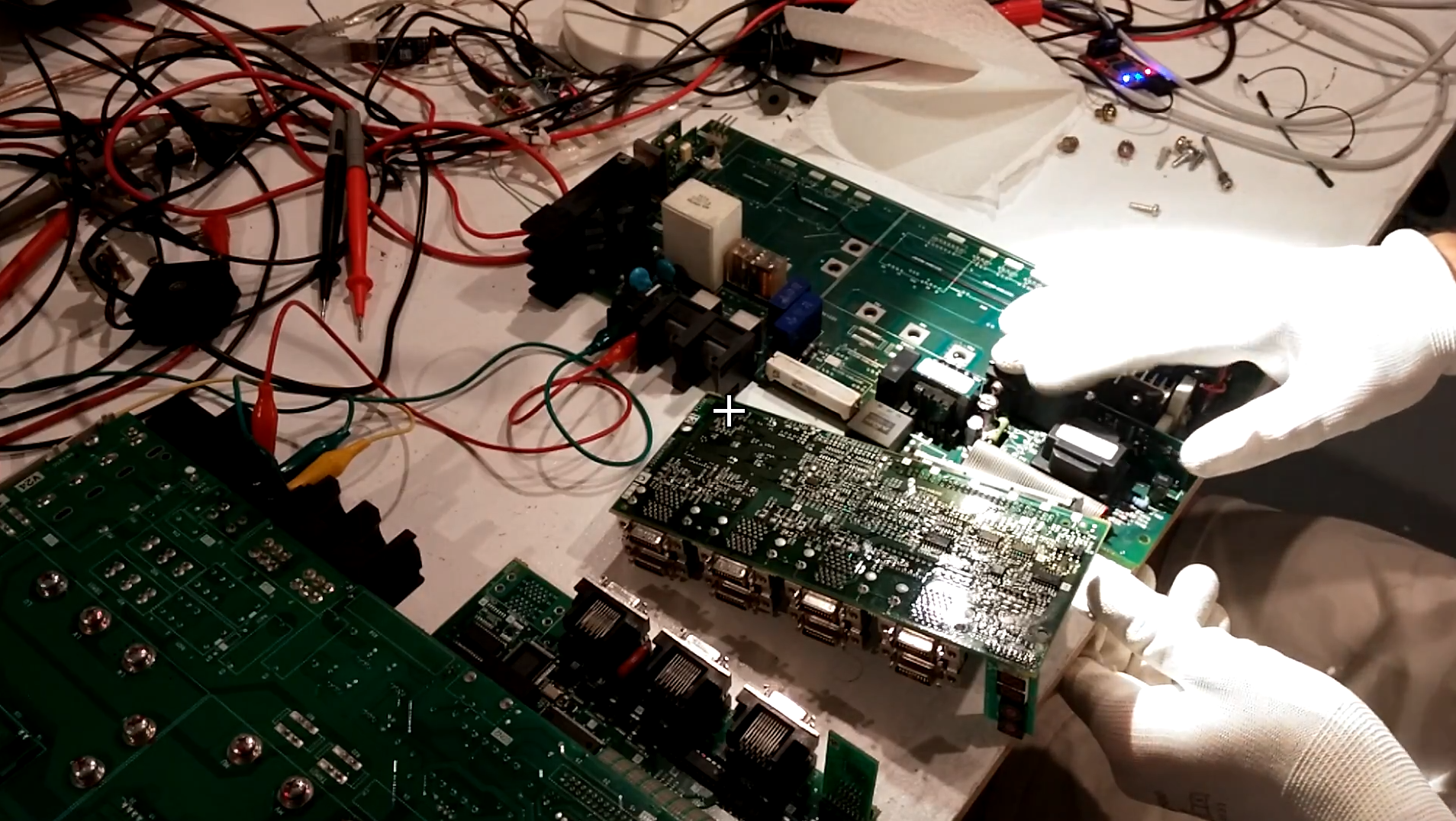
The Z axis driver was behaving in an undesirable fashion; namely, it was obstinate in its refusal to power up at all. The little seven-segment troubleshooting display [1] was blank, and the rest of the machine was unable to detect it.
A true professional was unavailable, so I brought it home to the lab to see if the traumatic experience of being prodded by an idiot with reckless disregard for the hippocratic oath might disturb it into functioning.
This is probably an obvious procedure to all, but I always try to give a failed board an extremely thorough visual inspection. The many of board failure modes that I've encountered have been such that careful scrutiny by eye and loupe would have located the source of the problem - and generally more rapidly than an electrical test. This is one of those cases.
Specifically, you might be looking looking for (clearly not an exhaustive list):
- Burn marks or soot on the inside casing during disassembly
- Any discoloration of the FR4 or resistors - areas that have been getting warm (especially focus on any capacitors near warm areas, as the lifespan of an electrolytic typically is halved every 10c rise)
- Subtle pock-marks or divots on chips that might indicate overheating
- Capacitor vent state and bulge, base size (failed caps without vents generally bulge at the bottom), and condition of leads - corroded lead area generally indicates electrolyte leakage
- Corrosion or whiskers on fine-pitch SMDs
- Miniscule cracks in through-hole solder joints subjected to mechanical strain
- Transformer winding discoloration
- Subtly snapped traces due to board flex
This yielded nothing unusual.
Normally, my next step would be to try to build up a rough schematic of the board. Generally this is done by tracing overlaid high-resolution images of the top and bottom, and ohming out any connections that aren't visible. This board, however, has a four layer stackup, making this somewhat difficult. I happened to already have a flying probe gantry from another project, and so I contemplated making some sort of vision-assisted automated continuity checker; but adding a second probe (to measure both ends of a trace) seemed an onerous task.
When working with critical legacy boards like this one, where replacements are nigh impossible to find, it's a good idea to replace all electrolytic capacitors every decade or so. In fact, the manual explicitly states that the caps should be swapped as part of preventative maintenance. This can prevent excessive ripple and noise from causing more serious issues.
And so, I made a DigiKey order with a number of replacements. Many parts were obsolete; modern equivalents had to be found.[2]
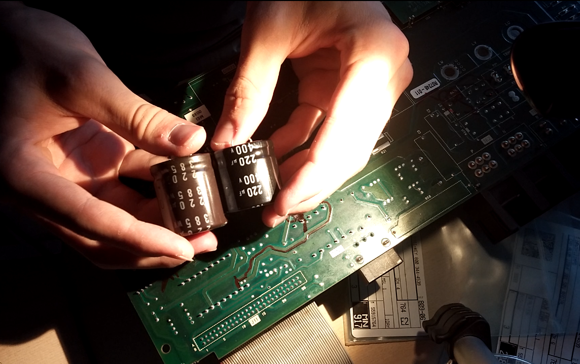
A half-hour of soldering and a drive to Barrie later, the board still exhibited rampant indolence when power was applied.
As any software developer will tell you, it's nearly impossible to troubleshoot a problem without being able to quickly replicate it. In this case, replicating the problem requires a 200v AC supply.
An isolated supply would be ideal, since that would prevent me from blowing up my oscilloscope due to ground loops - but none of my lab PSUs can get anywhere near 200v, and I don't have an isolation transformer.
So I did something a bit naughty.
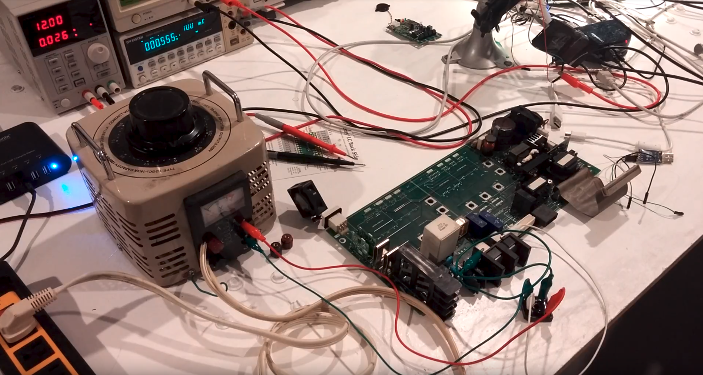
To my Korad floating lab supply I connected a standard 150W automotive inverter, and fed that into a variac set to ~170v. Voila! An ill-advised floating supply.
Uh, so then it appears that I blew up the ground clamp on my scope lead. I think I must have (in typical fashion) contacted something live with the ground ring of the scope probe.
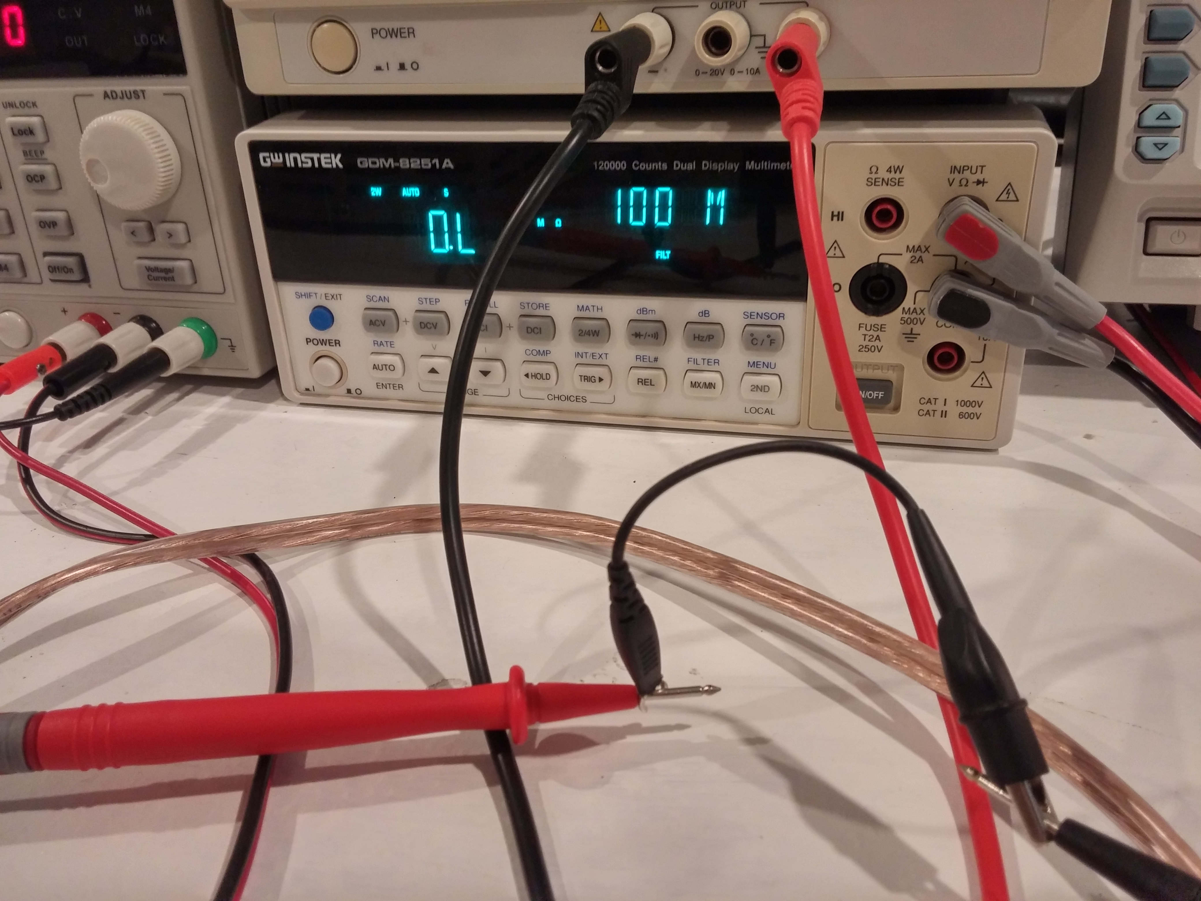
So I decided to not use my scope for this job anymore. I also decided to ditch the improvised floating supply and go directly to mains - accepting the slightly higher risk of being an unwilling participant in the movement of electrons.
Since the XY driver was functional and largely identical, I powered it up and began comparing every terminal with a bench multimeter. Bridge rectifier? Check. Transformer output? Null.
The SMPS mosfet gate was at 0 V. I traced that back to this interesting SMPS driver card, and was able to find the datasheet and application reference schematic for the M51996A driver chip.
Based on that reference schematic, the bootstrap capacitor voltage was varying wildly, indicative of a failure to bootstrap the driver properly.
SMPS systems slowly charge a capacitor as the main bus voltage rises for the first time; when the voltage across this bootstrap capacitor reaches ~20v, it dumps the capacitor into the mosfet's gate. If the electrolyte evaporates on that capacitor, there won't be enough energy to drive the gate and start the system proper.
Upon scrutiny, both the bootstrap and current-limit-monitoring electrolytic capacitors had strangely corroded terminals.
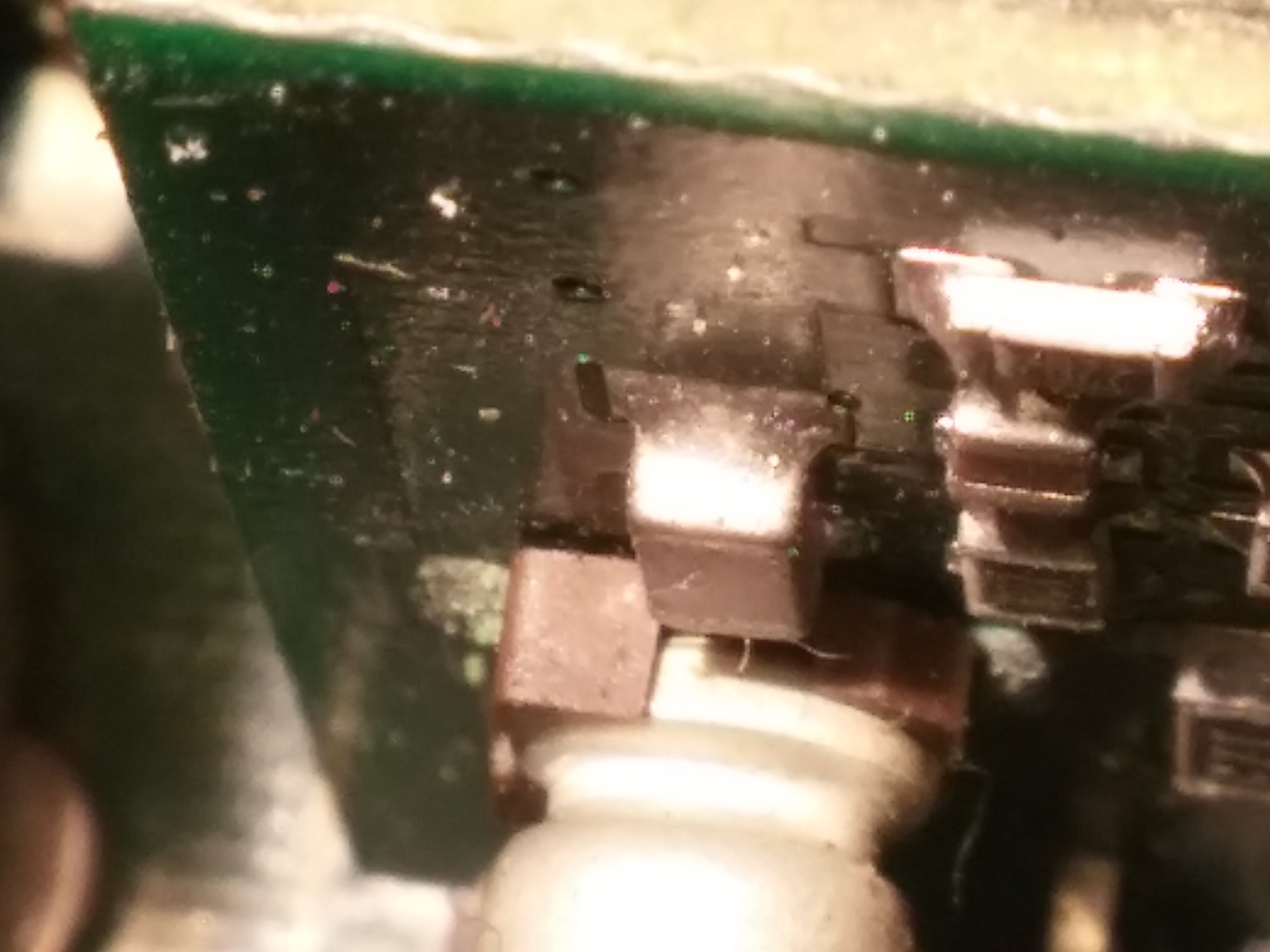
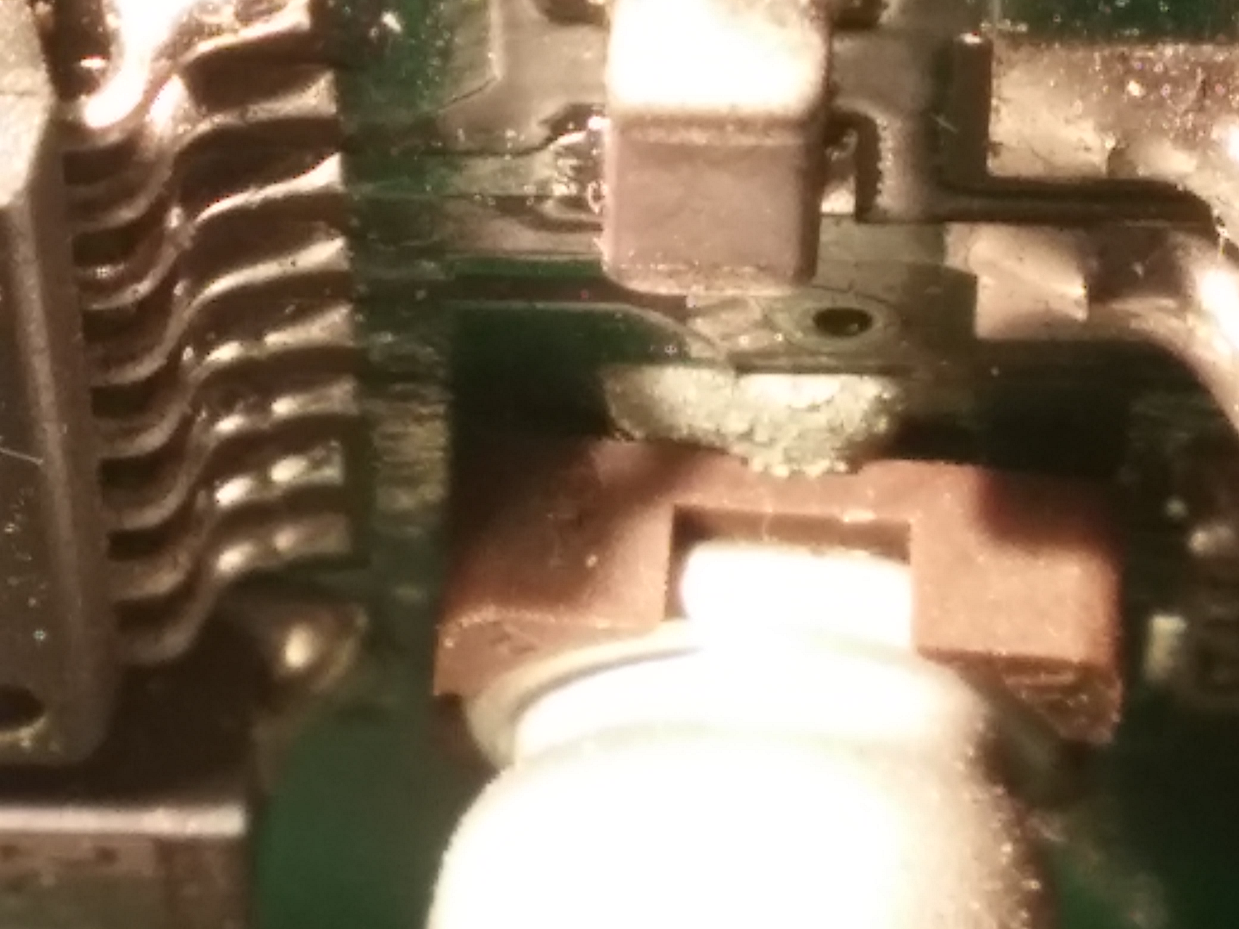
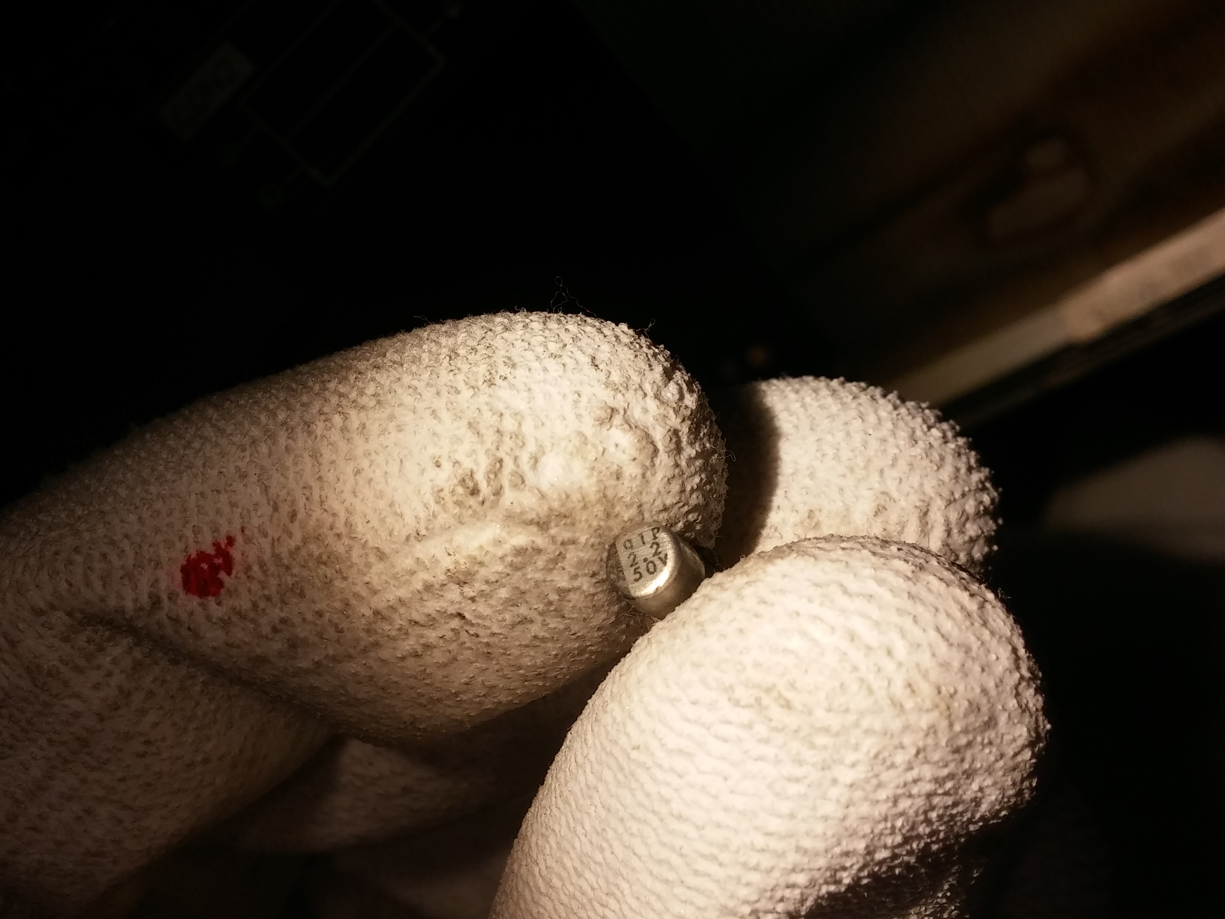
I didn't have an appropriate SMD replacement. In retrospect, it would have been a good idea to hot-glue these THT devices.
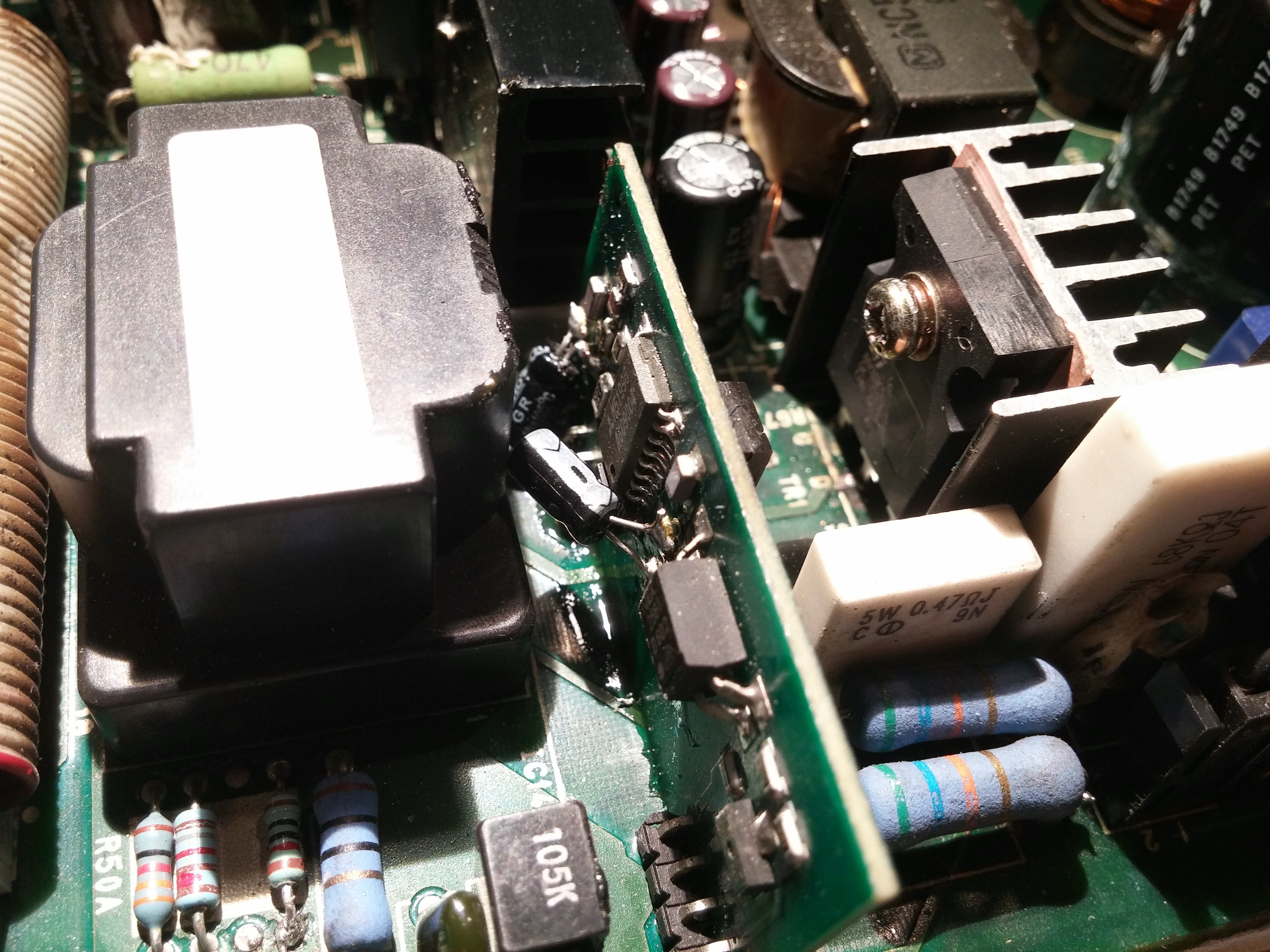 The board fired right up!
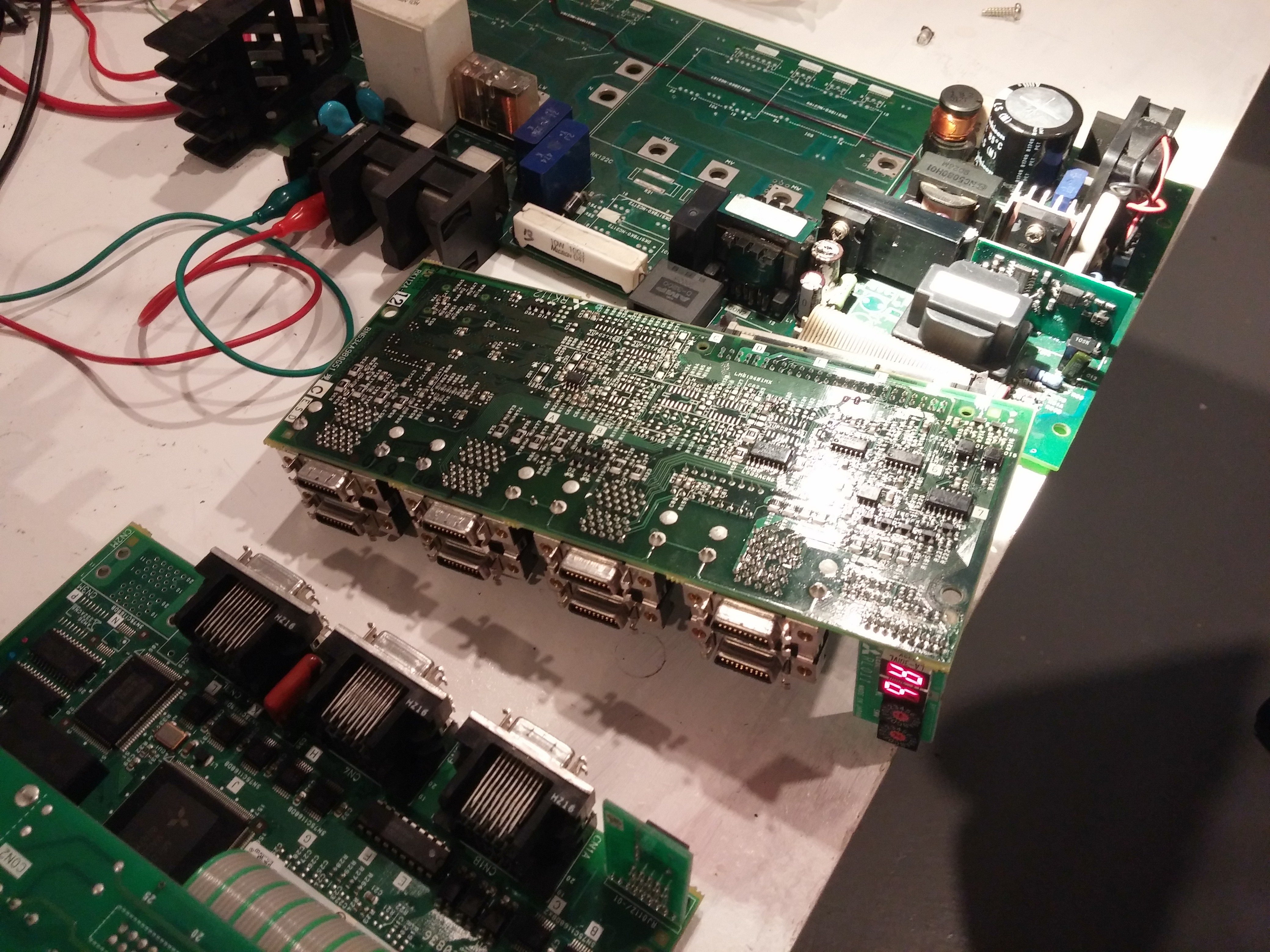
Wanna talk about this? Hit up xDBFB7 on IRC: irc.0xDBFB7.com:6667 #general
-
Really useful for servicing, actually. Something to think about for future products; having an error code display on the device itself was invaluable.
-
					"FMU-14S-ND","FMU-14S","DIODE ARRAY GP 400V 5A TO220F","","0","2.41000","$2.41"
					"497-2725-5-ND","STPS40H100CW","DIODE ARRAY SCHOTTKY 100V TO247","","0","4.20000","$4.20"
					"497-17085-ND","STW8N90K5","N-CHANNEL 900 V, 0.60 OHM TYP.,","","0","5.74000","$5.74"
					"493-5127-1-ND","UPJ1V820MED1TD","CAP ALUM 82UF 20% 35V RADIAL","","0","0.51000","$1.53"
					"399-15744-ND","ESL227M035AG8AA","CAP ALUM 220UF 20% 35V THRU HOLE","","0","0.48000","$1.44"
					"493-1900-ND","UPW1H121MPD","CAP ALUM 120UF 20% 50V RADIAL","","0","0.66000","$1.98"
					"493-2579-ND","LLS2G221MELB","CAP ALUM 220UF 20% 400V SNAP","","0","5.83000","$5.83"
					"1N4007-TPMSCT-ND","1N4007-TP","DIODE GEN PURP 1KV 1A DO41","","0","0.14800","$1.48"